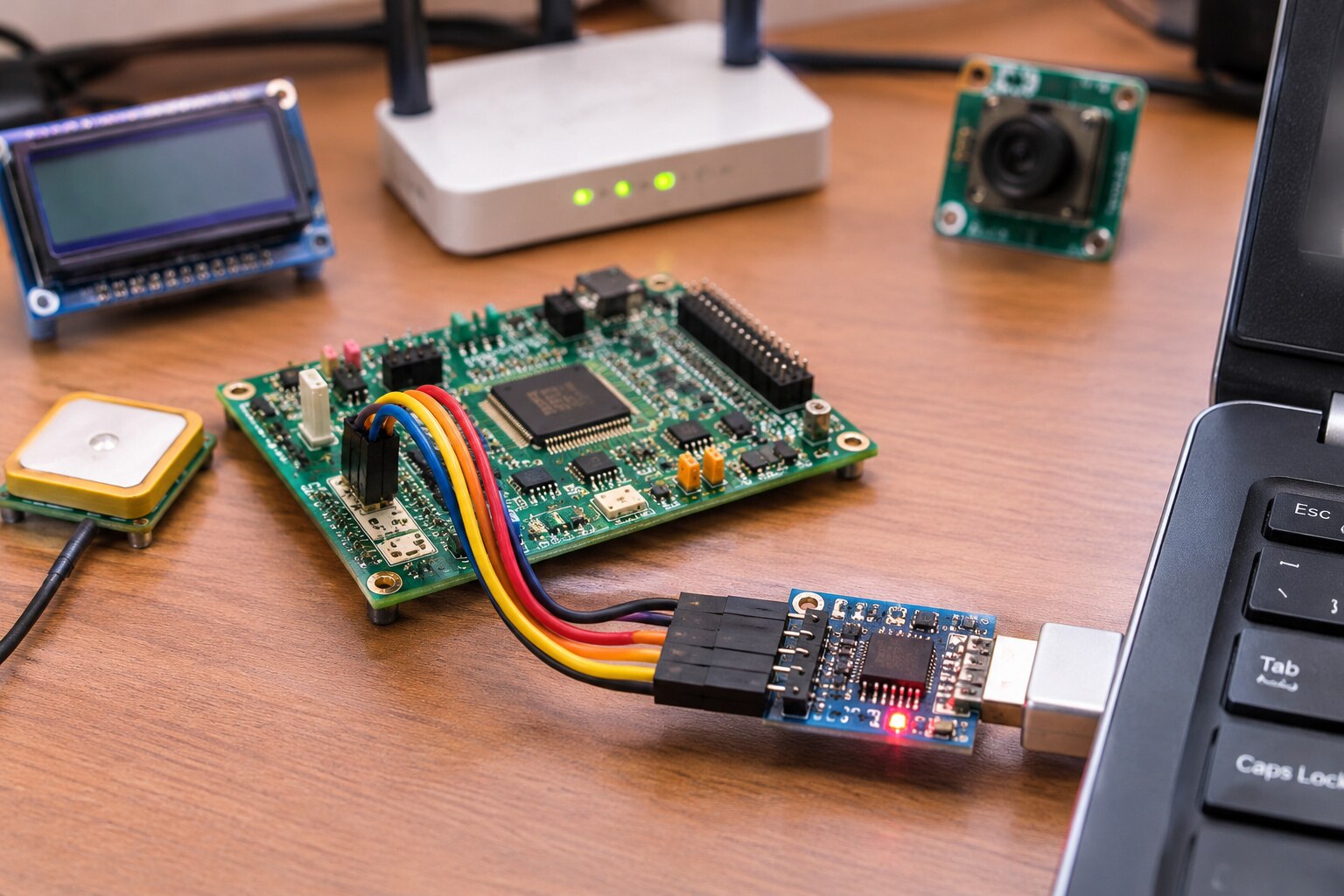
A UART link can connect a processor to a modem, GNSS receiver or service port, but bare UART signals are not automatically suitable for a cable between industrial enclosures. By the end, you will be able to match UART interface IC uses to Delhi equipment, choose between logic-level UART and RS-232, RS-485 or RS-422, and check the electrical, firmware and sourcing details that determine field reliability.
Key takeaways
- Match baud rate, data bits, parity and stop bits at both ends.
- Use RS-485 for multidrop buses and RS-232 for point-to-point links.
- Check logic voltage, connector pinout, cable length and termination before production.
- Request lifecycle status, traceability documents and tested samples for OEM builds.
How a UART IC Moves Data Inside Embedded Equipment
A UART converts parallel bytes inside a processor into a serial bit stream, then reconstructs received bits as parallel data. The transmitter adds a start bit, configured data bits, optional parity, and stop bit; the receiver checks that frame using a matching baud rate and format.
UART signalling alone does not specify cable voltage or connector type.
| Option | What it does | Where it fits |
|---|---|---|
| Microcontroller UART peripheral | Hardware inside the MCU handles framing, shifting, and receive/transmit buffering | One or more serial ports when the MCU has enough channels |
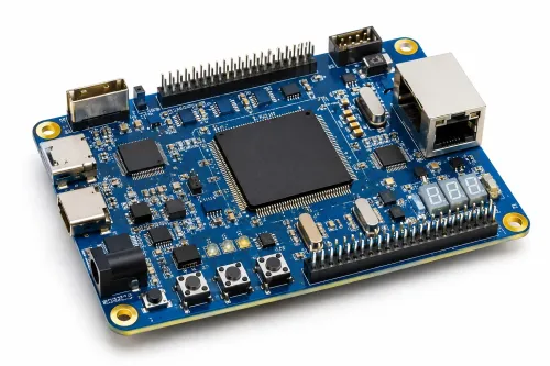
| Standalone UART IC | Adds UART channels, registers, and often FIFOs through an I²C or SPI host link | Extra serial ports or several peripherals without changing the processor |
| Physical-layer transceiver | Converts logic UART signals into RS-232, RS-485, or RS-422 electrical signalling | Cables between enclosures, differential links, or noisy installations |
UART interface IC uses therefore differ from transceiver uses. An SC16IS752, for example, supplies two UART channels but still needs an RS-232 or RS-485 transceiver for those cable standards. RS-232 uses inverted bipolar levels; RS-485 uses balanced differential signalling and supports multipoint buses. A direct MCU UART pin cannot drive either connector safely.
UART chips for embedded systems suit equipment that needs more serial ports, while a basic logic-level UART is enough for short board traces with compatible voltage thresholds.
Where UART Interfaces Fit in Delhi Equipment
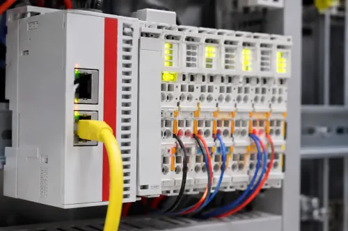
Industrial controllers, PLC expansion modules, energy meters, access-control panels, GPS terminals, GSM or LTE gateways, point-of-sale equipment, diagnostic ports and sensor gateways all use UART communication. A short board connection between a microcontroller and one peripheral needs only matching logic voltage, baud rate, data bits, parity and stop bits.
| Option | What it adds | When it applies |
|---|---|---|
| Logic-level UART | Direct single-ended TX and RX | Short connections inside one enclosure |
| Multi-channel UART IC | Extra UART ports, FIFO buffering and I²C or SPI control | A processor has too few UART peripherals |
| RS-232 transceiver | Bipolar, inverted cable signalling | A legacy PC, modem or service instrument |
| RS-485 or RS-422 transceiver | Differential signalling for cable distance and noise immunity | Separate enclosures, industrial sites or multidrop networks |
| UART-to-USB bridge | USB enumeration, descriptors, buffering and host-driver interaction | PC service, commissioning or firmware updates |
An external UART IC is useful when the processor lacks serial ports, needs independent FIFOs, or must expose several peripherals without replacing its microcontroller. A SC16IS752, for example, provides two UART channels through I²C or SPI; it does not replace the RS-232 or RS-485 transceiver at the cable.
For uart communication applications in delhi, choose RS-485 for long cables or noisy plant areas instead of bare UART. Add galvanic isolation when ground-potential differences, outdoor cable runs or fault-current paths threaten the controller; isolated power is required on the remote side.
Check each pin’s voltage rating. A 5 V transmitter can damage a 3.3 V receiver, so use a level translator or compatible transceiver. These decisions define uart interface ic applications for embedded equipment in delhi.
Choosing Logic-Level UART, RS-232, RS-485 or RS-422
Use logic-level UART for short board connections between a processor and a display, GNSS receiver, barcode engine or modem. Keep the traces short, share a ground, and match voltage levels; bare UART pins are not suitable for cables between cabinets.
These are common uart interface ic uses and a practical starting point for interface ics for electronic equipment.
| Option | What it means | When it applies |
|---|---|---|
| Logic-level UART | Single-ended 0 V and logic-supply signaling | Short PCB or board-to-board links |
| RS-232 | Inverted, bipolar, point-to-point signaling | Legacy instruments, service ports and nearby external equipment |
| RS-485 | Balanced differential, multipoint bus | Long cables, multidrop networks and industrial noise |
| RS-422 | Balanced differential, usually point-to-point | Long cable runs needing a dedicated driver and receiver |
Choose RS-232 when the device must communicate with a legacy PC, instrument or serial service tool. A MAX3232-class interface IC converts UART logic to RS-232 voltage levels; connecting the processor pin directly to the connector can damage the interface or produce no communication.
Choose RS-485 for several meters, separate enclosures or multiple devices on one bus. Add termination at the two physical ends, biasing where the transceiver design requires it, and a clear node-addressing scheme. RS-422 suits a long dedicated link, not a shared two-way bus.
For exposed Delhi installations, select a transceiver with a stated IEC 61000-4-2 test rating, then add an external TVS diode when the connector and cable environment demands it. Keep the protection return path short.
Electrical and Firmware Checks That Prevent UART Failures
Before releasing a UART design, verify the electrical limits, signal path, clock margin and firmware settings on the actual boards and cable assemblies.
1. Check every signal pin, not just the supply voltage. A 5 V transmitter can damage a 3.3 V receiver; confirm input thresholds, absolute maximum ratings and 5 V-tolerant pins. Add a level translator or validated series-resistor network where required.
2. Define protection at the connector. Use the specified ESD or TVS device, series resistors and a short return path to ground. For cables between enclosures, use an RS-485 transceiver with correct differential routing, termination and fail-safe biasing instead of exposing bare UART logic.
3. Calculate clock error at both endpoints. Include oscillator tolerance, temperature drift and baud-divider quantisation; check the total against the receiver’s sampling margin. A crystal or calibrated clock deserves review when selecting uart chips for embedded systems, especially at high or unusual baud rates.
4. Inspect the wiring against the real installation. Keep board-level UART traces short, share a suitable ground, cross noisy power paths at right angles and label TX-to-RX connections. Do not treat a UART header as a field bus.
5. Match baud rate, 5–8 data bits, parity and stop bits in firmware. Test framing, overrun and parity-error handling, then verify RTS/CTS wiring at both ends if buffering can fill.
6. For a USB service port, check enumeration, descriptors, FIFO depth, driver availability and operating-system support; a bridge is not merely a connector change. These checks prevent failures in UART communication applications in Delhi.
A Practical Selection and Sourcing Checklist for OEM Builds
Compare each candidate against the same operating case, not its headline baud rate. For UART interface IC applications for embedded equipment in Delhi, record voltage, channels, host bus, cable type, temperature range, package, lifecycle status and total support effort.
| Option | Best fit | Check before approval |
|---|---|---|
| Logic-level UART | Short board link to a processor or peripheral | I/O thresholds, 5 V tolerance, FIFO depth and baud-rate error |
| Multi-channel UART | Several serial peripherals behind SPI or I²C | Interrupt handling, channel isolation, driver support and reset behavior |
| USB-to-UART bridge | PC service, commissioning or firmware updates | USB descriptors, endpoint buffering, operating-system drivers and host compatibility |
| RS-485 transceiver | Long cable, separate enclosures or noisy industrial wiring | Unit load, fail-safe biasing, termination, ESD rating and TVS requirements |
Validate the selected part on the actual PCB, cable and firmware. A 5 V transmitter can damage a 3.3 V receiver even when both supply ranges look compatible; inspect every input’s absolute maximum and tolerance rating.
- Confirm the complete frame: baud rate, 5–8 data bits, parity and stop bits.
- Test cold start, brownout recovery, processor reset and unplug/replug recovery.
- Run maximum traffic until FIFO overflow, framing errors and interrupt latency are visible.
- Apply connector ESD with the intended TVS, return path and enclosure, not only the IC’s advertised IEC 61000-4-2 setup.
- Request date code, lot traceability, PCN policy, approved alternates and production samples.
For interface ICs for electronic equipment, ask MAXGTECH to quote the exact manufacturer part, package and revision, then retain the approval sample as your incoming-inspection reference. Service teams also need a pinout, driver package and field-replacement procedure.
Frequently asked questions
How does a UART IC move data inside embedded equipment?
It converts processor bytes into serial frames containing a start bit, data bits, optional parity and stop bit, then reconstructs received frames as bytes.
When should you choose logic-level UART, RS-232, RS-485 or RS-422?
Use logic-level UART for short board-level links, RS-232 for point-to-point equipment connections, RS-485 for multidrop networks, and RS-422 for differential point-to-point or one-driver links.
Which electrical and firmware checks prevent UART failures?
Confirm voltage levels, shared ground or isolation, TX-to-RX routing, baud rate, frame format, polarity, termination, cable limits and error handling.
What should OEMs check when sourcing UART interface ICs?
Verify the exact part number, package, temperature range, supply voltage, lifecycle status, authenticity, traceability, samples, test requirements and delivery plan.
Keywords