A Beckhoff terminal can show a healthy link while the EtherCAT master rejects its state, loses downstream devices, or reports watchdog and topology errors. You will learn how to separate network faults from PLC, power, wiring and machine-level failures, then isolate, replace and validate a suspect terminal without creating a second fault.
Key takeaways
- Check master, slave state and LED patterns before replacing a terminal.
- Separate cable, power, configuration and machine faults with controlled isolation.
- Replace one Beckhoff terminal at a time and document its position and settings.
- Confirm recovery in Operational state while the machine runs under normal load.
How a Beckhoff EtherCAT Terminal Stack Carries Network Traffic
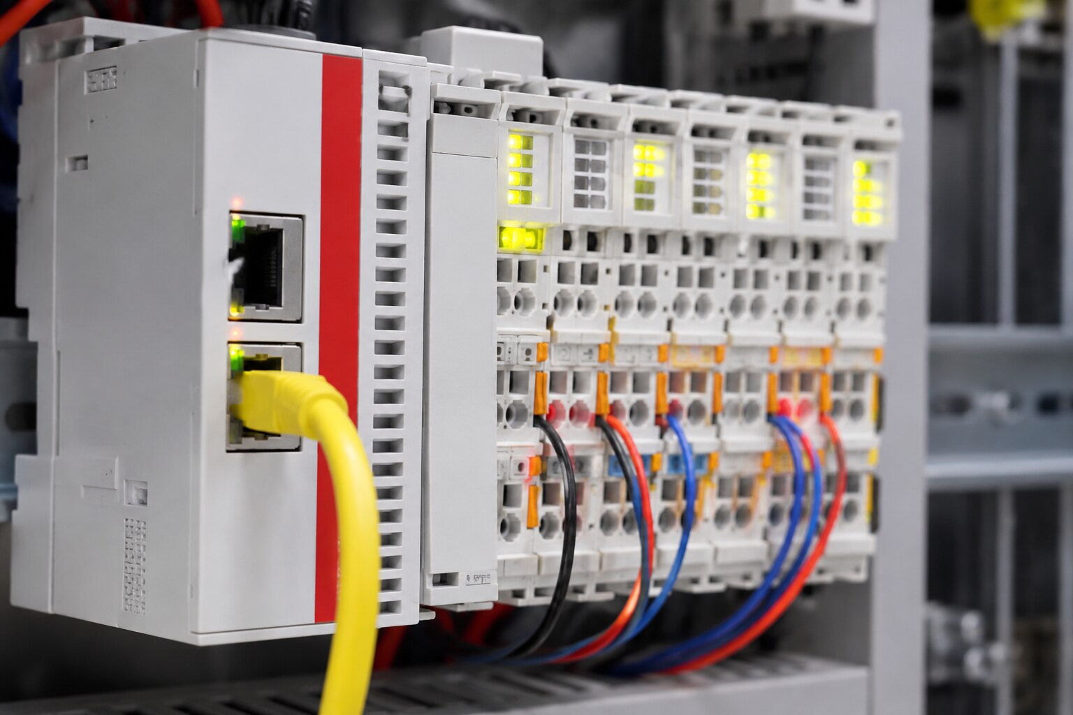
EtherCAT frames leave the EtherCAT master, pass through the coupler and each terminal, then return with process data inserted on the fly. The master controls the Init, Pre-Operational, Safe-Operational and Operational states; distributed clocks keep time-critical terminals synchronised. A green link LED proves only an electrical connection, not usable communication.
The physical chain has a hard stopping point. A failed terminal, loose E-bus contact, missing end terminal, incorrect coupler connection or damaged outgoing cable can block frames from every device downstream, even while upstream terminals appear healthy.
- E-bus power is separate from 24 V field power. If the stack exceeds the coupler’s specified E-bus current, scanning or startup can fail despite a correct voltage measurement at the external supply.
- A terminal can remain in PREOP or SAFEOP because of an Application Layer error, invalid configuration or missing process-data mapping, while its link LED stays green.
- Intermittent shielding, connector contamination, electromagnetic interference or copper damage can create CRC and lost-frame errors without extinguishing the link LED.
For beckhoff ethercat terminal network problems in delhi, compare the configured topology with the last responding station before replacing the master. A replacement terminal can alter station order and process-image offsets, so verify its exact order code, signal function, firmware, ESI description and PDO layout before scanning and returning the stack to Operational state.
Never remove terminals live; isolate power and follow the machine builder’s safety procedure.
Read the Master, Slave State and LED Evidence Before Replacing Anything
The decisive evidence is the combination of master state, terminal state, error counters and channel LEDs—not any single green light.
An Operational master with one terminal stuck in PREOP or SAFEOP points toward configuration, an Application Layer (AL) error or a device fault; a segment that stops at the same station points toward communication or hardware.
| Evidence | What it proves | Fault class |
|---|---|---|
| Master working-counter, lost-frame, CRC and link-state counters | Frames are missing, corrupted or not reaching the expected devices | Communication |
| AL status code, requested state, topology scan and process-data configuration | The terminal rejects its configured identity, PDO mapping or state transition | Configuration |
| Terminal RUN, ERR, power and channel LEDs, plus input/output diagnostics | The E-bus device has power, but one channel or terminal function reports a local fault | Terminal channel |
A green link LED proves electrical presence, not usable EtherCAT traffic. Compare the expected topology with the last responding station, then inspect the outgoing link, E-bus contacts and end terminal. Capture the counters before cycling power.
Read CoE object 0x10F3, the diagnosis history, when the terminal supports it; stored communication and application entries can preserve evidence lost during a reset. A distributed-clock alarm alone does not prove a defective terminal: check clock participation, topology, synchronization mode and jitter.
For beckhoff ethercat terminal faults in delhi, request the master diagnostic export, AL code, slave-state history and LED photographs together. That evidence separates a replacement-worthy channel fault from a cable, configuration or network problem.
Separate Cable, Power, Configuration and Machine Faults
A valid link LED does not prove healthy EtherCAT communication: separate the fault by checking master state, terminal state, power domain, and channel signal. If the master cannot reach Operational state, investigate transport, configuration, or supply before blaming the machine.
| Fault | Evidence that points to it | Confirming check |
|---|---|---|
| PLC or master | The PLC is stopped, its task watchdog is active, or the master does not command the expected state | Check the PLC run state, EtherCAT master diagnostics, and whether the entire bus is absent |
| Cable or topology | Link loss, rising CRC or error counters, or a topology scan that ends at one segment | Replace one cable with a known-good cable and inspect coupler-to-terminal links |
| E-bus supply | External 24 V field power is correct, but startup, scan, or downstream-terminal faults appear | Compare calculated stack current with the particular coupler’s E-bus rating |
| Configuration | A terminal remains in INIT, PREOP, or SAFEOP with an AL status code, identity mismatch, or missing PDO data | Verify station order, correct ESI file, terminal identity, PDO assignment, and startup parameters |
| Field device | The bus reaches OP, but one channel reads invalid or an actuator does not respond | Measure field voltage and 0 V, then check polarity, fuses, wiring, analog range, and safety-channel status |
Read CoE object 0x10F3 before power-cycling when supported; its diagnostic history can preserve a device-side event. A terminal in OP can still have an open sensor or dead actuator circuit.
A Safe Isolation and Beckhoff Terminal Replacement Sequence
Do not pull a terminal from a powered stack. Use this sequence to preserve evidence, identify the failed device and prevent a second fault.
1. Record the EtherCAT master’s slave state, AL status code, topology position, working-counter result, lost-frame and CRC counters, plus each terminal’s link, run and error LEDs. Save the configuration and diagnostic history before changing hardware.
2. Isolate machine energy under the builder’s safety procedure. Remove control and load power, verify zero voltage, and label the coupler, terminal order, field plugs and end terminal. A live EtherCAT link does not make live removal safe.
3. Compare the suspected terminal with the project record and nameplate. Match the complete order code, signal type, channel count, electrical ratings, process-data layout, firmware or revision requirement and wiring—not width or a similar prefix.
4. Check the engineering system for the correct ESI device description. If the identity or PDO assignment is unknown, install the matching ESI file before scanning; an apparently recognised device can still exchange the wrong process data.
5. Replace only the suspect terminal, keeping the original station position and field wiring. Restore power, scan for identity, then compare station order, PDO mapping, startup parameters and process-image offsets with the saved project. Do not accept an automatic rescan without review.
6. Transition the slave through Init, Pre-Operational, Safe-Operational and Operational while watching AL codes and counters. Stop if the original error returns or a new identity, watchdog or mapping fault appears.
For beckhoff ethercat terminal troubleshooting in delhi, MAXGTECH can help verify an imported part against the complete order code and documentation. For Beckhoff EtherCAT terminal replacement in Delhi, retain the removed terminal until the repair record proves the replacement is correct.
Prove Recovery in Operational State and Under Machine Load
Do not release the machine because the coupler reaches OP. Recovery is proven only when the EtherCAT master holds every required device in Operational state, process data remains valid, distributed-clock timing matches the baseline and the machine behaves correctly under load.
Run this acceptance check before production:
- Confirm the expected station order, terminal identities, PDO assignments and process-image sizes; reject an unexpected rescan or identity mismatch.
- Record master diagnostics during repeated machine cycles: working-counter values, lost frames, link-state changes, CRC errors and watchdog events must remain unchanged from the healthy baseline.
- Verify every required terminal stays in OP, with no new AL status code, error LED or channel diagnostic.
- Check distributed-clock status using the configured reference clock and participating devices; clock deviation and synchronization state must remain within the machine’s configured limits.
- Measure the terminal and field-circuit supplies under load, including 24 V, 0 V and actuator power. Confirm analog values, sensor states, polarity and output feedback at the channel.
- Test safety functions, guards, emergency stops and reset logic through the machine builder’s approved procedure.
Start with unloaded motion, then apply the normal production sequence and the highest expected simultaneous I/O demand. Watch diagnostics throughout; a network that passes a static scan but develops frame loss, jitter, voltage sag or watchdog trips under load is not recovered. Save the final topology, configuration, counters and test record.
Frequently asked questions
What evidence should you check before replacing a Beckhoff EtherCAT terminal?
Read the EtherCAT master state, slave state, diagnostic messages and terminal LED patterns. A green link LED proves electrical connection, not usable communication.
How can you separate cable, power, configuration and machine faults?
Inspect and test the cable, verify terminal supply voltages, compare the configured terminal stack with the physical order, and isolate the machine load from the network fault.
What is a safe Beckhoff EtherCAT terminal replacement sequence?
Back up the configuration, identify the exact terminal and position, isolate power, replace one module, restore the stack order and check the master diagnostics before restarting.
How do you prove an EtherCAT network has recovered?
Bring the network through Init, Pre-Operational, Safe-Operational and Operational states, then test distributed-clock operation and observe communication under normal machine load.
Keywords