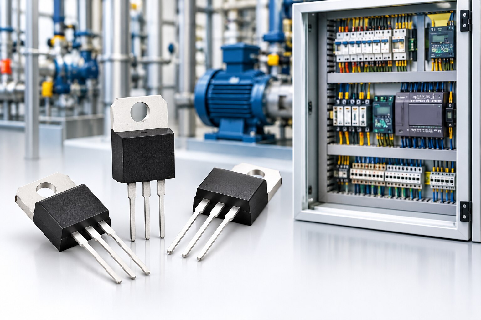
A BJT is a practical switch for many 24 V control-panel loads, but only when its base drive, heat, voltage spikes and turn-off behavior are designed around the actual load. You will be able to map common Delhi OEM equipment functions to suitable BJT circuits, size the device from datasheet conditions, and identify when another switching technology is safer or more efficient.
Key takeaways
- Use an NPN BJT for low-side switching of 24 V relays, solenoids and indicators.
- Calculate base current from forced beta, not the transistor’s headline gain.
- Add a flyback diode across every DC inductive load.
- Reject a BJT when heat, switching speed or fault energy exceeds its limits.
Where BJTs fit in 24 V industrial control equipment
A 24 V BJT is well suited to low-side switching, where an NPN transistor places the load between the positive rail and collector, with its emitter at 0 V and its base driven through a resistor. This arrangement suits relay coils, contactor-interface relays, solenoids, small DC valves, lamps, alarms and indicator circuits.
It is not a direct solution for mains loads. The same devices also provide current amplification, emitter-follower buffering, common-emitter signal gain and discrete interfaces between sensors, PLC outputs and loads.
- Drive a relay or solenoid when low cost, modest current and simple control matter.
- Buffer a weak sensor signal before feeding a comparator or controller input.
- Switch an indicator or alarm that needs more current than the logic output can supply.
- Build a small interface stage where the control signal and 0 V share a reference.
| Option | What it means | When it applies |
|---|---|---|
| BJT | Base current controls collector current | Low-current drivers, gain stages and simple 24 V interfaces |
| MOSFET | Voltage-driven switch with low conduction loss | Higher current, faster switching or limited controller current |
| Relay | Galvanically isolated mechanical contact | Different voltage domains or contact-level isolation |
| Contactor | High-power switching device | Motors, heaters and other substantial loads |
The practical case for BJT applications for industrial control equipment in Delhi remains strongest in these low-side functions. Bipolar transistor applications in Delhi control panels exposed to noise still need filtering, current limiting and clamping; IEC 61000-4-4 burst and IEC 61000-4-5 surge protection cannot be replaced by the transistor alone.
Build the switching and interface circuit around the load
Put a 24 V relay coil between the positive rail and the collector of an NPN transistor; connect the emitter to 0 V and drive the base through a resistor. This low-side arrangement keeps the control signal referenced to the same rail and suits a BJT for industrial control applications.
Add a base pull-down resistor so the load stays off while the controller is starting.
| Load or signal | Circuit choice | Design consequence |
|---|---|---|
| Relay, solenoid or small DC valve | NPN low-side switch with a flyback diode | The diode protects the transistor, but slows coil release |
| Lamp or panel indicator | Series resistor with the lamp and transistor switch | Calculate the resistor from supply voltage and lamp current |
| Sensor or PLC signal | Base resistor, pull-up or pull-down, and a defined 0 V reference | Limit input current and prevent a floating state |
For an inductive load, place the flyback diode directly across the coil, with its cathode at the positive rail. Use a zener, TVS or diode-plus-zener clamp when the equipment needs faster release; verify that the resulting collector voltage remains below VCEO and the switching safe operating area.
Never use this stage to switch a mains load directly.
BJT circuits for equipment exposed to panel noise need more than a transistor. Add input filtering, current limiting and a suitable clamp, then define the connection between signal 0 V and chassis. Check the completed interface against IEC 61000-4-4 electrical fast transients and IEC 61000-4-5 surge conditions.
An optocoupler provides isolation, but design its output from minimum CTR at the operating temperature and LED current, with enough margin for reliable turn-off.
Size the BJT from base drive, heat and fault conditions
Start with the worst-case load current, not the transistor’s headline gain. For a saturated NPN switch, choose a forced beta from the datasheet’s saturation test, such as 10, then calculate base current: IB = IC / 10. A 120 mA coil therefore needs at least 12 mA of base current.
Calculate the base resistor as RB = (Vdrive − VBE) / IB, then check that the PLC or microcontroller output can source that current without exceeding its voltage and current limits.
Verify the design in this order:
- Use the maximum coil, lamp or valve current, including supply tolerance and cold-load inrush.
- Check VCE(sat) at your chosen IC and IB. Conduction loss is P = VCE(sat) × IC; a 2 V drop at 3 A dissipates 6 W.
- Calculate junction temperature from ambient temperature, package thermal resistance and power dissipation. Reject the part if the result exceeds its rated junction temperature.
- Check VCEO, SOA and pulse ratings against supply surges, wiring faults and a shorted load.
- Confirm turn-off time at the required switching frequency; stored charge can matter in saturated BJTs.
A Darlington reduces controller base current but brings two VBE drops, higher saturation voltage and slower turn-off. Include those losses rather than treating it as a direct substitute. Specify BJT components for OEM systems by package, pinout, gain bin, temperature range and saturation test conditions; a part-number substitution can change heat removal and pin order.
Parallel BJTs need emitter ballast or active current sharing because negative VBE temperature coefficient causes current hogging.
Choose a BJT only where its trade-offs fit the control task
A BJT is preferable for a low-side 24 V driver when the load is modest, switching speed is low, and the controller can supply base current. Use an NPN with the emitter at 0 V and the load between the positive rail and collector.
This suits relay coils, contactor-interface relays, solenoids, lamps and small DC valves—not mains switching.
| Device | Choose it when | Why not choose a BJT |
|---|---|---|
| BJT | You need a low-cost, low-current driver or analog gain stage | Base current, saturation storage and heat reduce efficiency |
| MOSFET | The load current, switching frequency or duty cycle is high | Gate-drive design may cost more; a BJT can be simpler for small loads |
| Relay or contactor | You need galvanic isolation, very low off-state leakage or mains/load switching | Contacts wear, arc and switch slowly |
| Optocoupler | You need signal isolation between controller and field circuit | It is an interface, not a substitute for the output transistor or load protection |
For bipolar transistor applications in Delhi, do not treat the BJT as noise protection. IEC 61000-4-4 burst and IEC 61000-4-5 surge immunity may require filtering, current limiting, clamping and a defined 0 V-to-chassis arrangement.
Add a flyback diode when slow coil release is acceptable; use a TVS or diode-zener clamp for faster release, keeping the collector voltage below VCEO and switching SOA limits. Choose a PNP high-side stage only when its level-shift circuit protects the controller pin.
Specify, inspect and support BJT components in an OEM design
Approve BJT components for OEM systems only after the design record, supplier evidence and physical samples agree. A part number alone cannot protect a control panel from a wrong pinout, weak gain margin or counterfeit marking.
1. Record the exact manufacturer part number, package, pinout, VCEO, IC, SOA, power dissipation, operating temperature range and gain bin. State the intended load current, forced beta, base current, VCE(sat) test conditions and calculated junction temperature.
2. Verify the schematic and layout against the physical device. Check collector, base and emitter orientation, package thermal path, PCB spacing, creepage and clearance. A TO-92, SOT-23, TO-220 and surface-mount power package are not interchangeable by appearance or nominal transistor type.
3. Require lot or date traceability and a certificate of conformance. Incoming inspection should sample markings, dimensions and electrical characteristics, including gain, leakage, breakdown voltage and saturation voltage. A diode test alone can miss a remarked transistor.
4. Test the complete stage with the real coil, valve, lamp or relay. Confirm flyback clamping, turn-off time, base pull-down action and heat at the highest ambient temperature. For Darlington devices, include their higher VCE(sat), two VBE drops and stored charge.
5. Treat IEC 61000-4-4 burst and IEC 61000-4-5 surge immunity as system tests. Add filtering, current limiting, clamping, a defined 0-V/chassis strategy and PCB spacing where needed; a BJT input is not noise protection.
For imported BJT applications for industrial control equipment in Delhi, MAXGTECH can help reconcile approved specifications with lot documentation before production release.
Frequently asked questions
Where do BJTs fit in 24 V industrial control equipment?
NPN BJTs fit low-side switching for relay coils, contactor-interface relays, solenoids, small DC valves, lamps, alarms and indicators.
How should you build a BJT switching and interface circuit?
Place the load between the positive rail and collector, connect the emitter to 0 V, drive the base through a resistor, and add a flyback diode across inductive DC loads.
How do you size a BJT for an industrial control circuit?
Check required collector current, forced beta, base-drive current, saturation voltage, power dissipation, temperature rise and fault conditions.
When is a BJT the wrong choice for industrial control equipment?
Choose another device when the circuit needs very low conduction loss, high-speed switching, minimal drive current or greater tolerance of overload energy.
Keywords