Choosing the wrong transistor technology can increase inverter losses, heatsink size, switching stress, and field failures even when the voltage and current ratings look adequate. You will be able to match MOSFETs or IGBTs to the DC-link voltage, motor type, PWM frequency, thermal design, protection strategy, and purchasing format.
Key takeaways
- Start with DC-link voltage and motor current, not the transistor name.
- Calculate conduction and switching losses at the actual PWM operating point.
- Match the diode, package, and commutation pattern to the inverter design.
- Give Delhi suppliers voltage, current, frequency, thermal, and traceability requirements.
Start with the DC link, not the transistor label
A 48 V DC link usually favours MOSFETs: low RDS(on) keeps I²R conduction loss low, and their fast switching makes high PWM frequency practical. Start the IGBT vs MOSFET for motor control decision with this bus voltage, not the transistor label.
| DC-link class | Practical direction | Main reason |
|---|---|---|
| 48 V | MOSFET | Low RDS(on) limits conduction loss; high PWM frequency is practical |
| 400–415 V AC input, 540–590 V DC | 600/650 V devices | Common industrial class, but voltage margin remains essential |
| 1,200 V DC | Often IGBT | IGBT conduction loss and available industrial modules can outweigh MOSFET switching benefits |
A rectified 400–415 V three-phase supply produces about 540–590 V DC. A 650 V device still needs margin for line tolerance, regenerative rise, switching overshoot, and braking; check bus surge and repetitive safe-operating-area data, not voltage rating alone.
At this voltage, a silicon MOSFET may need a large die to reduce RDS(on), increasing cost and capacitance, while an IGBT accepts higher conduction voltage through VCE(sat) but can remain economical at moderate PWM frequency.
At 1,200 V, IGBTs often become practical for industrial drives; high-voltage MOSFETs remain relevant when switching frequency and efficiency justify their cost. Check voltage rating, overload current, bus surge, and short-circuit capability together. An industrial power transistor comparison is a calculation from the actual inverter, not a universal low-power-MOSFET/high-power-IGBT rule.
Calculate conduction and switching loss at the real operating point
Use the motor’s RMS current during the actual conduction interval, not the datasheet’s continuous-current headline. For a MOSFET, Pcond ≈ Irms² × RDS(on)(Tj) × duty cycle ÷ parallel-device count. RDS(on) rises with junction temperature, so calculate at the expected Tj and include acceleration and regenerative peaks.
For an IGBT, Pcond ≈ VCE(sat)(I,Tj) × Iavg × duty cycle; its voltage-drop model makes it competitive at 600–1,200 V and moderate current.
| Loss factor | MOSFET | IGBT |
|---|---|---|
| Switching | Psw ≈ fPWM(Eon + Eoff); no minority-carrier tail | Turn-off tail current raises Eoff; field-stop designs reduce, not eliminate, it |
| Frequency | Usually favours higher PWM frequency | Usually favours moderate PWM frequency |
| Gate drive | Compare Qg and driver loss, Qg × Vgate × fPWM | Compare Qg, +15 V drive, and turn-off requirements |
For an IGBT vs MOSFET for motor control decision, request curves at your DC-link voltage, gate resistance, Tj, current waveform, and PWM frequency. Dead time that is too long increases diode conduction and distortion; too little causes shoot-through.
Check the complete thermal path: junction-to-case resistance, heatsink interface, mounting torque, enclosure ambient, and cooling airflow. Bus-bar inductance creates voltage overshoot; gate-loop inductance increases ringing and false turn-on. A cooler device on paper can fail inside a poorly mounted, poorly cooled inverter.
Match the switch and diode to the motor and commutation pattern
A 400–415 V induction-motor inverter running at moderate PWM frequency and enduring acceleration overload commonly suits an IGBT module. Its separately specified antiparallel diode must carry freewheel current during braking, regeneration, commutation, and reverse current.
PMSM and BLDC drives have higher electrical commutation frequency, frequent regenerative current, and compact inverter layouts. When the bus voltage and switching frequency are lower, MOSFETs gain a stronger case through lower switching loss and shorter current paths.
Switched-reluctance motors demand closer scrutiny: rapid current chopping, asymmetric bridges, and hard commutation make switching loss and diode recovery behaviour decisive.
| Drive case | Device tendency | Check before choosing |
|---|---|---|
| Induction motor | IGBT module | 400–415 V duty, acceleration overload, diode recovery |
| PMSM or BLDC | MOSFET at lower bus voltage and higher frequency | Body-diode Qrr, regeneration, layout overshoot |
| Switched-reluctance | Either technology | Chopping speed, asymmetric bridge, hard commutation |
A discrete MOSFET normally relies on its intrinsic body diode. At high current, its forward loss and Qrr can be limiting; soft recovery reduces turn-on loss and voltage overshoot. Add an external diode when the body diode’s current, recovery, or thermal rating fails the waveform.
- Set gate-driver blanking below the IGBT’s specified short-circuit withstand time; coordinate desaturation detection, current limiting, and fault-clearing time.
- For MOSFETs, verify SOA at the actual drain voltage and junction temperature; no universal short-circuit time exists.
- Limit dead time: too much increases diode conduction and distortion, while too little causes shoot-through.
Choose the package that completes the inverter
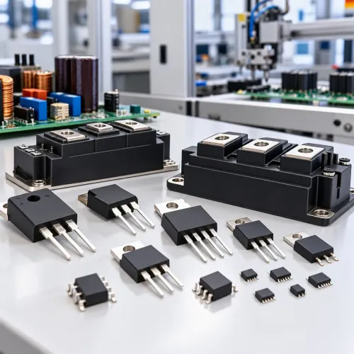
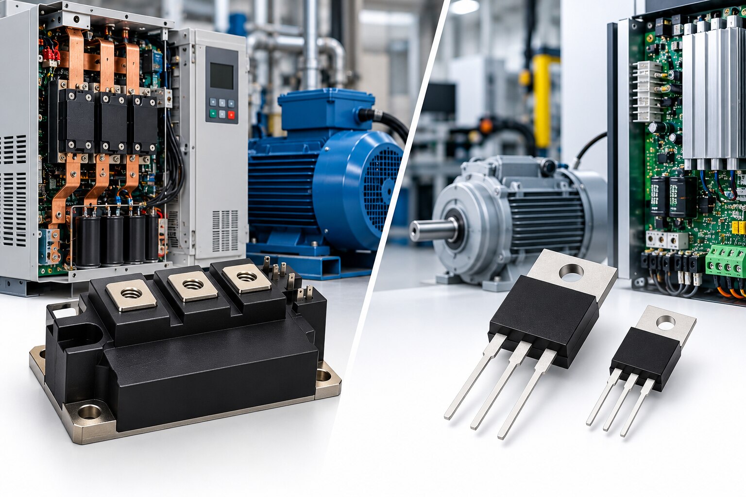
At 48 V or in a lower-power custom inverter, discrete MOSFETs usually give the simplest, lowest-cost layout. Discrete IGBTs suit higher-voltage designs, while modules reduce assembly risk.
| Option | Practical advantage | Main compromise |
|---|---|---|
| Discrete MOSFETs | Flexible, easy to parallel | PCB layout and protection are yours |
| Discrete IGBTs | Low high-voltage conduction loss | Careful gate and emitter layout |
| Half-bridge module | Matched high-side/low-side pair | Less mechanical flexibility |
| Six-pack module | Three bridges in one package | Replacing one failed leg may mean replacing the module |
| Intelligent power module | Switches, drivers, protection, and isolation in one unit | Fixed ratings, interfaces, and service method |
Parallel MOSFETs when I²RDS(on) dominates. Their positive temperature coefficient usually pushes current toward cooler devices, improving sharing; match gate paths and source inductance anyway.
Parallel IGBTs require closer VCE(sat), gate-charge, and switching matching. Keep emitter paths symmetrical and add individual emitter ballast when imbalance threatens current concentration.
For a three-phase drive, a six-pack or IPM shortens commutation loops and integrates isolation, gate drivers, undervoltage lockout, overcurrent, and thermal protection. Six discrete switches offer easier field replacement but demand six coordinated drivers, isolation channels, protection circuits, and tightly matched layout.
Do not choose by VGS(th). Verify the MOSFET’s specified 10–12 V drive or logic-level rating; an IGBT typically needs +15 V turn-on, possible negative turn-off bias, Miller immunity, and controlled common-source or emitter inductance.
SiC MOSFETs are separate from silicon: control dv/dt, EMC, insulation, bearing current, and motor-cable effects. This industrial power transistor comparison must include those controls.
Turn the technical comparison into a Delhi sourcing specification
Send a quotation request built around the inverter, not just “IGBT” or “MOSFET.” State the DC-link class, phase-current waveform, overload events, motor, switching conditions, mechanical envelope, and traceability standard.
- DC link: 48 V, 400–415 V, 650 V, or 1,200 V; peak and RMS phase current; acceleration and regenerative overload duration.
- Motor: induction, PMSM, BLDC, or switched-reluctance; PWM frequency; junction-temperature target; gate-drive voltage; diode type, softness, and Qrr requirement.
- Construction: discrete package or module outline, isolation voltage, heatsink interface, mounting limits, cooling method, and short-circuit protection method.
| Parameter | Put this in the request | Why it matters |
|---|---|---|
| Voltage and current | DC-link class, peak/RMS current, bus surge | Prevents an unsuitable voltage or pulse rating |
| Loss data | Conduction and switching-loss curves at your voltage, temperature, gate resistance, and PWM frequency | Enables real thermal comparison |
| Protection | SOA, short-circuit withstand time, desaturation blanking, fault-clearing time | Coordinates the gate driver with fault survival |
| Traceability | Date code, manufacturer lot identity, original packing, moisture-control history, authorised distribution records | Reduces counterfeit and storage risk |
A diode or resistance check cannot expose a remarked, reclaimed, obsolete, or dynamically weak device; only switching, SOA, thermal, and lot evidence can. For an IGBT vs MOSFET supplier in Delhi, MAXGTECH can support comparison when you provide these details, whether evaluating an IGBT supplier in Delhi or a MOSFET supplier in Delhi.
The value is matching one documented device or module, not declaring a universal winner.
Frequently asked questions
Should you choose an IGBT or MOSFET for a 48 V motor-control DC link?
A 48 V DC link usually favours MOSFETs because low RDS(on) reduces I²R conduction loss and fast switching supports higher PWM frequency.
How do you compare IGBT and MOSFET losses in an industrial inverter?
Calculate conduction loss and switching loss at the real bus voltage, motor current, duty cycle, PWM frequency, junction temperature, and commutation pattern.
Why does the diode matter when selecting an IGBT or MOSFET?
The freewheel diode affects reverse-recovery loss, voltage overshoot, EMI, and dead-time behaviour, so match it to the motor current and commutation pattern.
What should you include in a Delhi sourcing specification for power transistors?
State DC-link voltage, peak and continuous current, PWM frequency, short-circuit rating, thermal limits, package, diode requirements, lifecycle needs, and traceability documents.
Keywords